
TM 5-2410-241-23-2
0174
INSTALLATION CONTINUED
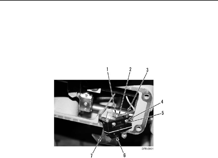
17. Install brake switch (Figure 12, Item 6), two washers (Figure 12, Item 5), and screws (Figure 12, Item 4) on
bracket (Figure 12, Item 7).
N OT E
Install electrical connections and route harness as noted during removal.
18. Install two wires (Figure 12, Item 3), washers (Figure 12, Item 2), and screws (Figure 12, Item 1) on brake
switch assembly (Figure 12, Item 6).
Figure 12. Brake Switch Wires.
0174