
TM 5-2410-241-23-2
0174
REMOVAL CONTINUED
N OT E
Note harness routing to aid installation.
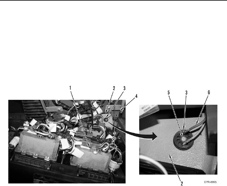
17. Position instrument panel (Figure 7, Item 1) from instrument panel hinge (Figure 7, Item 4).
18. Remove bolt (Figure 7, Item 5) from grommet (Figure 7, Item 3).
19. Remove grommet (Figure 7, Item 3) and harness (Figure 7, Item 6) from brake pedal housing (Figure 7,
Item 2).
20. Remove harness (Figure 7, Item 6) from machine.
21. Position instrument panel (Figure 7, Item 1) on instrument panel hinge (Figure 7, Item 4).
Figure 7. Brake Switch Harness Grommet.
0174
END OF TASK
CLEANING AND INSPECTION
000174
Clean and inspect all parts IAW Mechanical General Maintenance Instructions (WP 0295).
END OF TASK