
TM 5-2410-241-23-2
0174
REMOVAL CONTINUED
N OT E
Note harness routing to aid installation.
Tag and mark all electrical connections to aid installation.
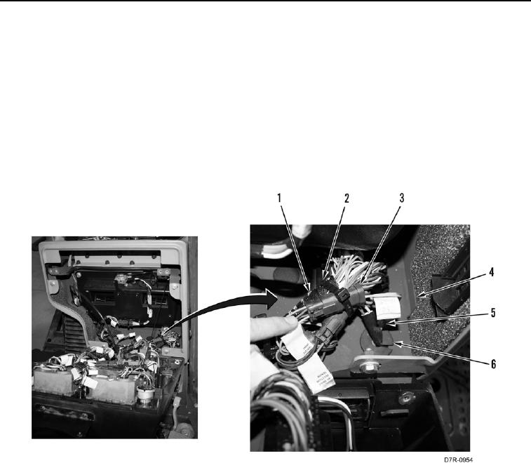
13. Remove tiedown strap (Figure 6, Item 2) from connector (Figure 6, Item 3). Discard tiedown strap.
14. Disconnect connector (Figure 6, Item 1) from connector (Figure 6, Item 3).
15. Remove grommet (Figure 6, Item 6) from instrument panel (Figure 6, Item 4).
16. Position harness (Figure 6, Item 5) and connector (Figure 6, Item 3) out from instrument panel (Figure 6,
Item 4).
Figure 6. Harness Connector.
0174