
14
TM 5-2410-241-23-2
FIELD MAINTENANCE
-
SWITCH AND HARNESS ASSEMBLY (SERVICE BRAKE) REPLACEMENT
0174
Removal, Cleaning and Inspection, Installation
INITIAL SETUP
References
Tools and Special Tools
0
0
Tool Kit, General Mechanic's
WP 0295
0
(WP 0302, Item 65)
0
Equipment Condition
0
Materials/Parts
Machine parked (TM 5-2410-241-10)
0
0
Rag, Wiping (WP 0303, Item 24)
0
Drawing Required
0
Tag, Marker (WP 0303, Item 34)
0
TM 5-2410-241-24P, Figure 110, 119
Tiedown Strap (WP 0303, Item 36)
0
0
Estimated Time to Complete
0
1.5 Hr
0
REMOVAL
000174
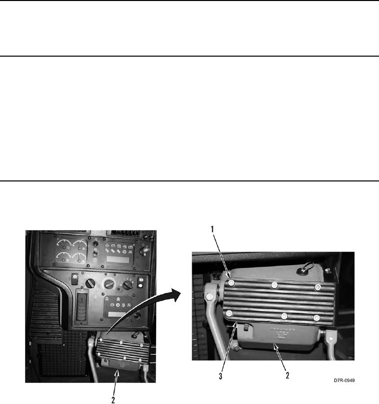
1. Remove six bolts (Figure 1, Item 1) and plate (Figure 1, Item 3) from brake pedal housing (Figure 1, Item 2).
Figure 1. Plate.
0174