• Home
  • Download PDF
  • Order CD-ROM
  • Order in Print
Figure 3. Brake Switch Wires.
Figure 5. Instrument Panel Upper Bolts.

Field Maintenance Manual D7R Dozer Type I With Winch and Type II With Ripper
Page Navigation
  999    1000    1001    1002    1003  1004  1005    1006    1007    1008    1009  
img
.
TM 5-2410-241-23-2
0174
REMOVAL CONTINUED
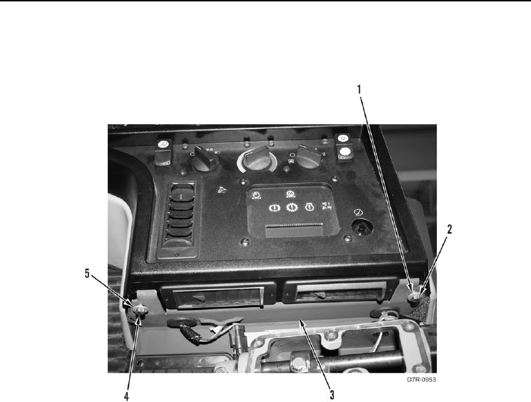
6. Remove bolt (Figure 4, Item 2) and washer (Figure 4, Item 1) from instrument panel (Figure 4, Item 3).
7. Remove bolt (Figure 4, Item 4) and washer (Figure 4, Item 5) from instrument panel (Figure 4, Item 3).
Figure 4. Instrument Panel Lower Bolts.
0174
0174-4


Privacy Statement
Press Release
Contact

© Copyright Integrated Publishing, Inc.. All Rights Reserved.