
TM 5-2410-241-23-2
0174
REMOVAL CONTINUED
N OT E
Note harness routing to aid installation.
Tag and mark all electrical connections to aid installation.
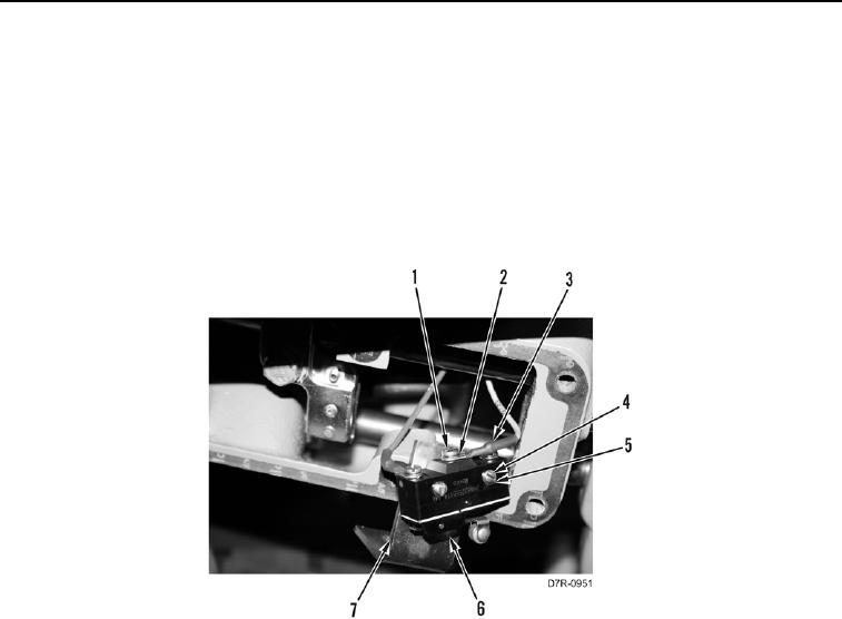
4. Remove two screws (Figure 3, Item 1), washers (Figure 3, Item 2), and wires (Figure 3, Item 3) from brake
switch assembly (Figure 3, Item 6). Position wires aside.
5. Remove two screws (Figure 3, Item 4), washers (Figure 3, Item 5), and brake switch assembly (Figure 3,
Item 6) from bracket (Figure 3, Item 7).
Figure 3. Brake Switch Wires.
0174