• Home
  • Download PDF
  • Order CD-ROM
  • Order in Print
Figure 10. Instrument Panel Upper Bolts.
Figure 12. Brake Switch Wires.

Field Maintenance Manual D7R Dozer Type I With Winch and Type II With Ripper
Page Navigation
  1006    1007    1008    1009    1010  1011  1012    1013    1014    1015    1016  
img
.
TM 5-2410-241-23-2
0174
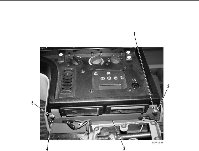
INSTALLATION CONTINUED
15. Install washer (Figure 11, Item 5) and bolt (Figure 11, Item 4) on instrument panel (Figure 11, Item 3).
16. Install washer (Figure 11, Item 1) and bolt (Figure 11, Item 2) on instrument panel (Figure 11, Item 3).
Figure 11. Instrument Panel Lower Bolts.
0174
0174-11


Privacy Statement
Press Release
Contact

© Copyright Integrated Publishing, Inc.. All Rights Reserved.