• Home
  • Download PDF
  • Order CD-ROM
  • Order in Print
Figure 13. Brake Switch Assembly.
ECM (POWERTRAIN) REPLACEMENT

Field Maintenance Manual D7R Dozer Type I With Winch and Type II With Ripper
Page Navigation
  1009    1010    1011    1012    1013  1014  1015    1016    1017    1018    1019  
img
.
TM 5-2410-241-23-2
0174
INSTALLATION CONTINUED
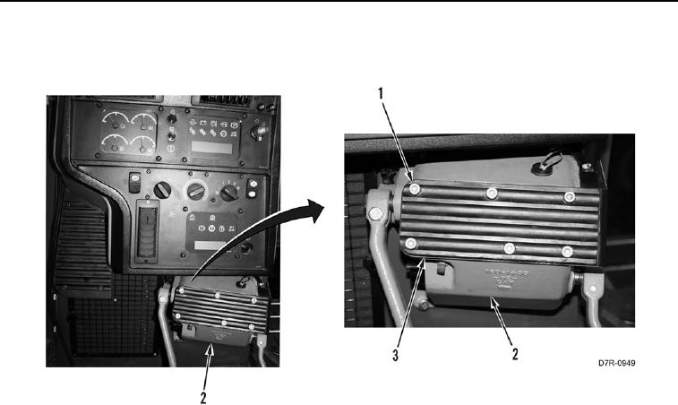
21. Install plate (Figure 14, Item 3) and six bolts (Figure 14, Item 1) on brake pedal housing (Figure 14, Item 2).
Figure 14. Plate.
0174
END OF TASK
FOLLOW-ON TASKS
000174
Verify correct operation of machine (TM 5-2410-241-10).
END OF TASK
END OF WORK PACKAGE
0174-14


Privacy Statement
Press Release
Contact

© Copyright Integrated Publishing, Inc.. All Rights Reserved.