
TM 5-2410-241-23-2
0175
INSTALLATION
000175
N OT E
Install electrical connectors as noted during removal.
Install bracket as noted during removal.
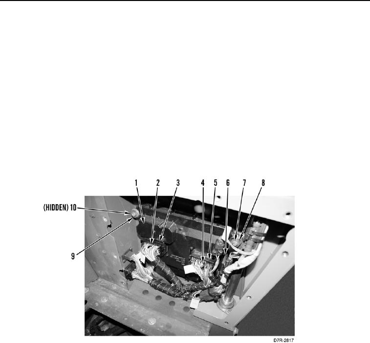
1. Install eight isolators (Figure 4, Item 9) and four spacers (Figure 4, Item 10) on powertrain ECM (Figure 4,
Item 1).
2. Install powertrain ECM (Figure 4, Item 1), two washers (Figure 4, Item 8), and rear mounting bolts (Figure 4,
Item 7), on machine.
3. Install bracket (Figure 4, Item 6), two washers (Figure 4, Item 8), and front mounting bolts (Figure 4, Item 7) on
powertrain ECM (Figure 4, Item 1).
4. Plug in connector (Figure 4, Item 5) and tighten bolt (Figure 4, Item 4) until connector is installed on powertrain
ECM (Figure 4, Item 1).
5. Plug in connector (Figure 4, Item 3) and tighten bolt (Figure 4, Item 2) until connector is installed on powertrain
ECM (Figure 4, Item 1).
Figure 4. ECM (Powertrain).
0175