
TM 5-2410-241-23-2
0179
REMOVAL CONTINUED
N OT E
Note harness routing to aid installation.
Tag and mark all electrical connectors to aid installation.
Mark location and note number of tiedown straps before removal.
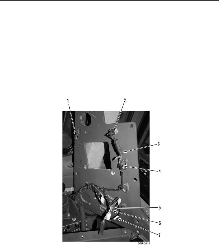
9. Remove tiedown straps (Figure 5, Item 4) from harness (Figure 5, Item 3) and upper right access panel
(Figure 5, Item 1). Discard tiedown straps.
10. Disconnect horn switch (Figure 5, Item 2) connector from harness (Figure 5, Item 3).
11. Disconnect indicator lamp (Figure 5, Item 7) connector from harness (Figure 5, Item 3).
12. Remove nut (Figure 5, Item 6), washer (Figure 5, Item 5), and indicator lamp (Figure 5, Item 7) from upper right
access panel (Figure 5, Item 1).
13. Remove upper right access panel (Figure 5, Item 1) from machine.
Figure 5. Switch Panel Harness.
0179