
TM 5-2410-241-23-2
0179
INSTALLATION CONTINUED
N OT E
Install electrical connectors and roue harnesses as noted during removal.
t
Install tiedown straps as noted during removal.
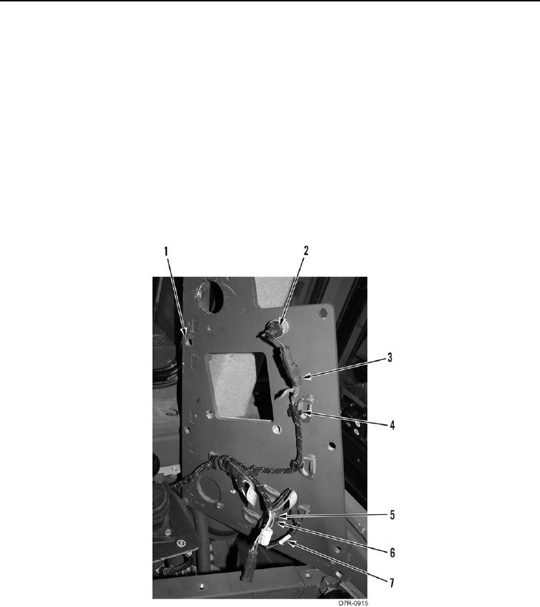
5. Position harness (Figure 8, Item 3) on machine.
6. Position upper right access panel (Figure 8, Item 1) on machine.
7. Connect horn switch (Figure 8, Item 2) connector on harness (Figure 8, Item 3).
8. Connect indicator lamp (Figure 8, Item 7) connector on harness (Figure 8, Item 3).
9. Install indicator lamp (Figure 8, Item 7), washer (Figure 8, Item 5), and nut (Figure 8, Item 6) on upper right
access panel (Figure 8, Item 1).
10. Install harness (Figure 8, Item 3) and new tiedown straps (Figure 8, Item 4) on upper right access panel
(Figure 8, Item 1).
Figure 8. Switch Panel Harness.
0179