
TM 5-2410-241-23-2
0179
INSTALLATION
000179
N OT E
Install electrical connectors and roue harnesses as noted during removal.
t
Install tiedown straps as noted during removal.
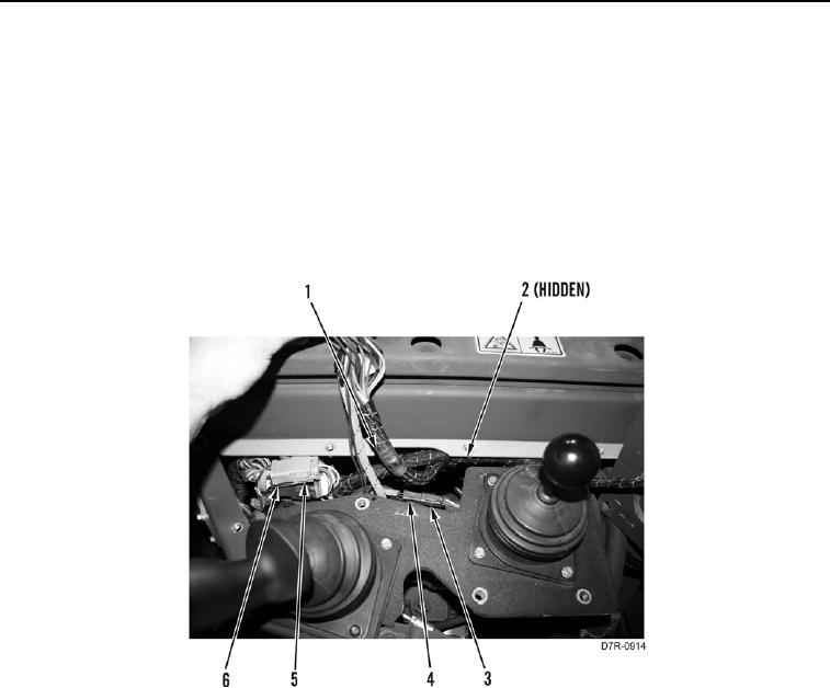
1. Position harness (Figure 7, Item 1) on machine.
2. Connect three connectors (Figure 7, Item 5) on three connectors (Figure 7, Item 6).
3. Connect connector (Figure 7, Item 3) on connector (Figure 7, Item 4).
4. Install new tiedown straps (Figure 7, Item 2) on harness (Figure 7, Item 1).
Figure 7. Harness Connectors.
0179