
TM 5-2410-241-23-2
0187
REMOVAL CONTINUED
N OT E
Note hose routing to aid installation.
Tag and mark all hoses to aid installation.
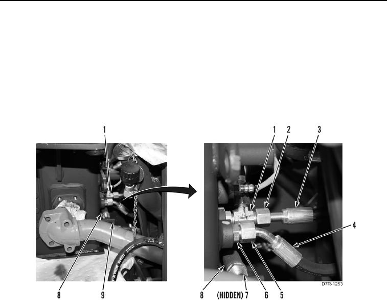
12. Loosen tube nut (Figure 4, Item 5) and remove hose (Figure 4, Item 4) from fitting (Figure 4, Item 6).
13. Loosen tube nut (Figure 4, Item 7) and remove hose (Figure 4, Item 8) from hydraulic tank (Figure 4, Item 9).
Position hose aside.
14. Loosen two tube nuts (Figure 4, Item 2) and remove two hoses (Figure 4, Item 3) from fitting (Figure 4, Item 1).
Position hoses aside.
Figure 4. Hydraulic Lines.
0187