
TM 5-2410-241-23-2
0187
REMOVAL CONTINUED
N OT E
Note hose routing to aid installation.
Tag and mark all hose connections to aid installation.
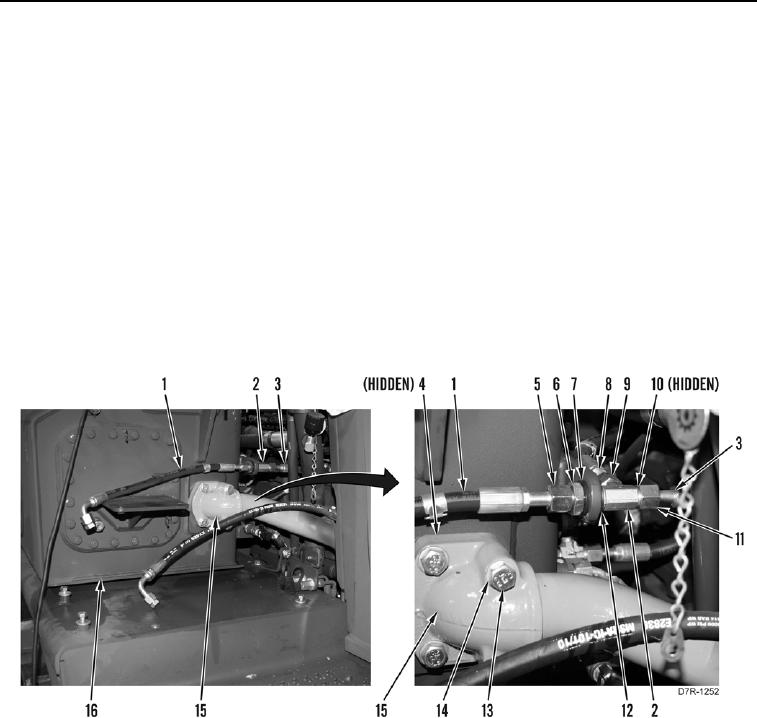
6. Loosen tube nut (Figure 3, Item 5) and remove hose (Figure 3, Item 1) from fitting (Figure 3, Item 2).
7. Loosen tube nut (Figure 3, Item 11) and remove hose (Figure 3, Item 3) from fitting (Figure 3, Item 2). Position
hose aside.
8. Loosen tube nut (Figure 3, Item 9) and remove hose (Figure 3, Item 8) from fitting (Figure 3, Item 2). Position
hose aside.
9. Remove nut (Figure 3, Item 6), washer (Figure 3, Item 7), and fitting (Figure 3, Item 2) from hydraulic tank
(Figure 3, Item 16).
10. Remove three O-rings (Figure 3, Item 10) and washer (Figure 3, Item 12) from fitting (Figure 3, Item 2). Discard
O-rings.
11. Remove four bolts (Figure 3, Item 13), washers (Figure 3, Item 14), elbow (Figure 3, Item 15), and gasket
(Figure 3, Item 4) from hydraulic tank (Figure 3, Item 16). Discard gasket. Position elbow aside.
Figure 3. Elbow.
0187