
TM 5-2410-241-23-2
0187
DISASSEMBLY CONTINUED
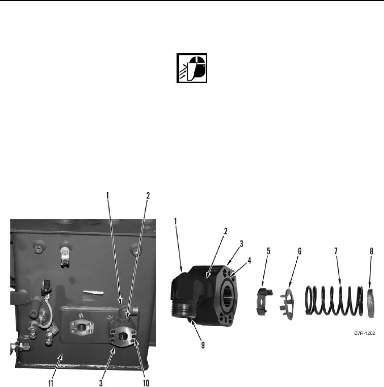
10. Loosen nut (Figure 13, Item 2) on elbow (Figure 13, Item 1).
WARN I N G
Valve block and spacers are under spring pressure. Note position and orientation of parts
as they are removed.
11. Remove two bolts (Figure 13, Item 10), valve block (Figure 13, Item 3), spacer (Figure 13, Item 5), spacer
(Figure 13, Item 6), spring (Figure 13, Item 7), and washer (Figure 13, Item 8) from hydraulic tank (Figure 13,
Item 11).
12. Remove O-ring (Figure 13, Item 4) from valve block (Figure 13, Item 3). Discard O-ring.
13. Remove elbow (Figure 13, Item 1) from valve block (Figure 13, Item 3).
14. Remove two O-rings (Figure 13, Item 9) from elbow (Figure 13, Item 1). Discard O-rings.
Figure 13. Hydraulic Tank Valve Block.
0187