
TM 5-2410-241-23-2
0187
DISASSEMBLY CONTINUED
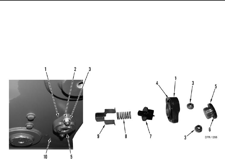
36. Remove drain plug (Figure 19, Item 5) from safety valve housing (Figure 19, Item 1).
37. Remove O-ring (Figure 19, Item 6) from drain plug (Figure 19, Item 5). Discard O-ring.
38. Remove two locknuts (Figure 19, Item 3), washers (Figure 19, Item 2), and safety valve housing (Figure 19,
Item 1) from hydraulic tank (Figure 19, Item 10). Discard locknuts.
39. Remove bracket (Figure 19, Item 9), spring (Figure 19, Item 8), and valve (Figure 19, Item 7) from safety valve
housing (Figure 19, Item 1).
40. Remove gasket (Figure 19, Item 4) from safety valve housing (Figure 19, Item 1). Discard gasket.
Figure 19. Hydraulic Tank Safety Drain Valve.
0187