
TM 5-2410-241-23-2
0187
ASSEMBLY
000187
N OT E
Steps 1 - 4 will assemble one internal pipeassembly. Follow same steps for an additional
internal pipe assembly.
Install internal pipe, filter support, and O-rings as noted during disassembly.
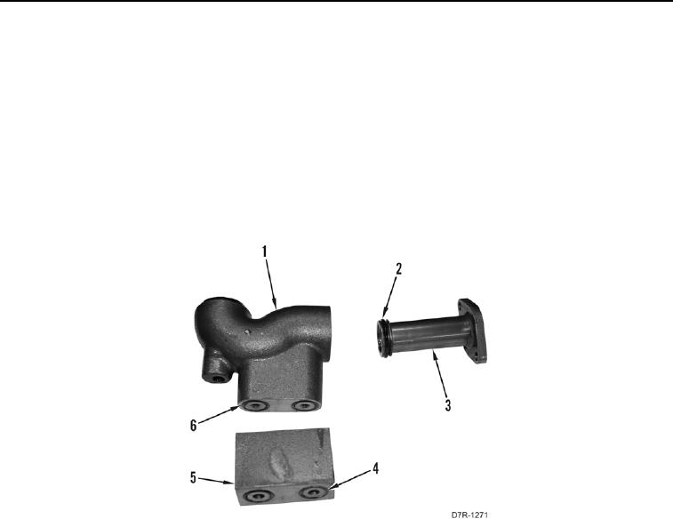
1. Install two new O-rings (Figure 23, Item 2) on pipe (Figure 23, Item 3).
2. Install pipe (Figure 23, Item 3) on filter support (Figure 23, Item 1).
3. Install two new O-rings (Figure 23, Item 6) on filter support (Figure 23, Item 1).
4. Install two new O-rings (Figure 23, Item 4) on block (Figure 23, Item 5).
.
Figure 23. Hydraulic Tank Internal Pipes.
0187