
TM 5-2410-241-23-2
0187
ASSEMBLY CONTINUED
N OT E
Install level gauge components as noted during disassembly.
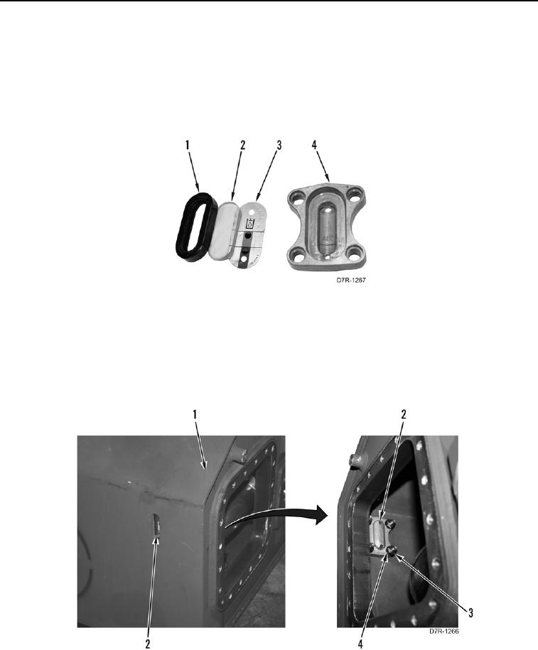
15. Install sight glass (Figure 27, Item 2) on new gasket (Figure 27, Item 1).
16. Install plate (Figure 27, Item 3) and gasket (Figure 27, Item 1) on level gauge housing (Figure 27, Item 4).
Figure 27. Level Gauge.
0187
N OT E
Install level gauge as noted during disassembly.
17. Install level gauge (Figure 28, Item 2), four washers (Figure 28, Item 4), and new locknuts (Figure 28, Item 3)
on hydraulic tank (Figure 28, Item 1).
Figure 28. Hydraulic Tank Level Gauge.
0187