• Home
  • Download PDF
  • Order CD-ROM
  • Order in Print
Figure 32. Hydraulic Tank Valve Block.
Figure 35. Hydraulic Tank Breather.

Field Maintenance Manual D7R Dozer Type I With Winch and Type II With Ripper
Page Navigation
  1107    1108    1109    1110    1111  1112  1113    1114    1115    1116    1117  
img
.
TM 5-2410-241-23-2
0187
ASSEMBLY CONTINUED
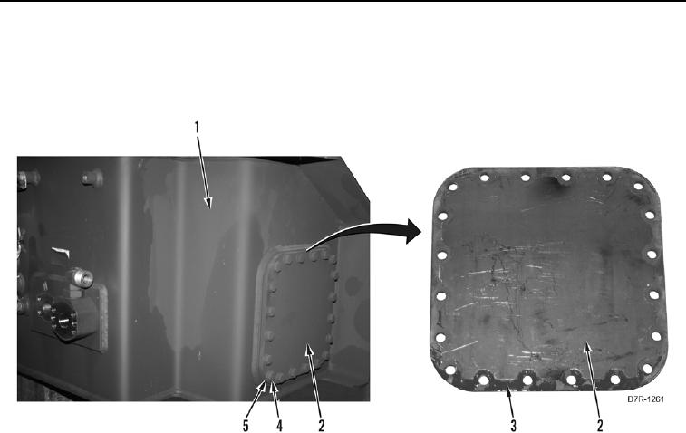
40. Install new gasket (Figure 33, Item 3) on cover plate (Figure 33, Item 2).
41. Install cover plate (Figure 33, Item 2), 20 washers (Figure 33, Item 5), and bolts (Figure 33, Item 4) on
hydraulic tank (Figure 33, Item 1).
Figure 33. Hydraulic Tank Rear Cover Plate.
0187
0187-29


Privacy Statement
Press Release
Contact

© Copyright Integrated Publishing, Inc.. All Rights Reserved.