
TM 5-2410-241-23-2
0187
ASSEMBLY CONTINUED
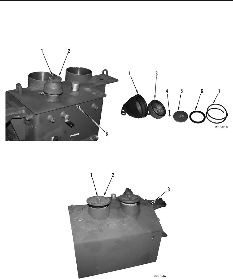
45. Install inner cap (Figure 36, Item 3), ball (Figure 36, Item 4), spacer (Figure 36, Item 5), and new seal
(Figure 36, Item 6) on cap (Figure 36, Item 1).
46. Install spring clip (Figure 36, Item 7) on cap (Figure 36, Item 1).
47. Install cap (Figure 36, Item 1) on hydraulic tank (Figure 36, Item 8) and lower lever (Figure 36, Item 2).
Figure 36. Hydraulic Tank Cap.
0187
48. Install two filter assemblies (Figure 37, Item 2) and tighten two bolts (Figure 37, Item 1) on hydraulic tank
(Figure 37, Item 3).
Figure 37. Hydraulic Tank Filters.
0187
END OF TASK