• Home
  • Download PDF
  • Order CD-ROM
  • Order in Print
Figure 38. Hydraulic Tank.
Figure 41. Hydraulic Lines.

Field Maintenance Manual D7R Dozer Type I With Winch and Type II With Ripper
Page Navigation
  1111    1112    1113    1114    1115  1116  1117    1118    1119    1120    1121  
img
.
TM 5-2410-241-23-2
0187
INSTALLATION CONTINUED
N OT E
Install hoses as noted during removal.
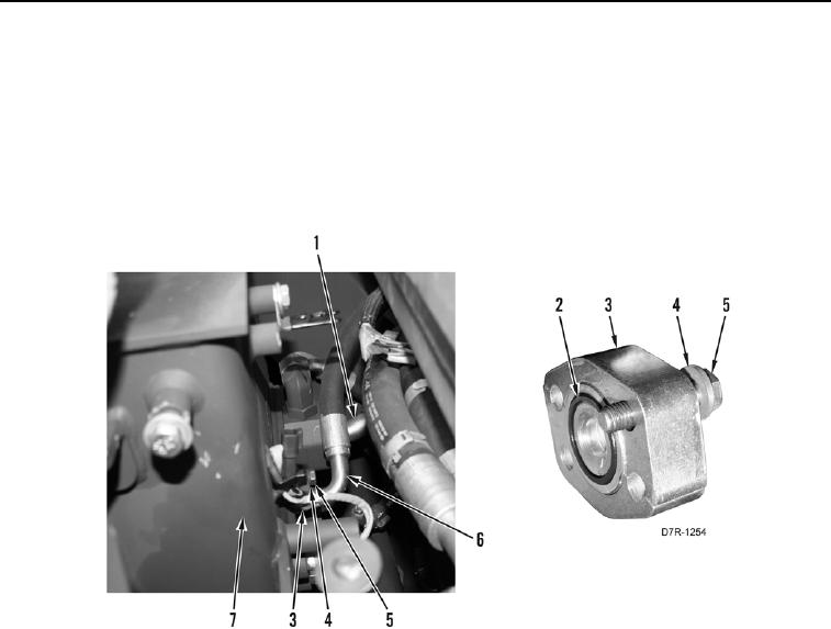
5. Install two new O-rings (Figure 40, Item 2) on two hoses (Figure 40, Items 6 and 1).
6. Install two hoses (Figure 40, Items 1 and 6), two flanges (Figure 40, Item 3), eight washers (Figure 40, Item 4),
and bolts (Figure 40, Item 5) on hydraulic tank (Figure 40, Item 7).
Figure 40. Flange.
0187
0187-33


Privacy Statement
Press Release
Contact

© Copyright Integrated Publishing, Inc.. All Rights Reserved.