
TM 5-2410-241-23-2
0187
INSTALLATION CONTINUED
N OT E
Install hoses as noted during removal.
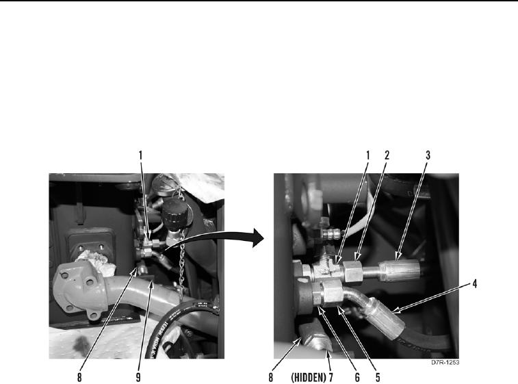
7. Install two hoses (Figure 41, Item 3) and tighten tube nuts (Figure 41, Item 2) on fitting (Figure 41, Item 1).
8. Install hose (Figure 41, Item 8) and tighten tube nut (Figure 41, Item 7) on hydraulic tank (Figure 41, Item 9).
9. Install hose (Figure 41, Item 4) and tighten tube nut (Figure 41, Item 5) on fitting (Figure 41, Item 6).
Figure 41. Hydraulic Lines.
0187