
TM 5-2410-241-23-2
0187
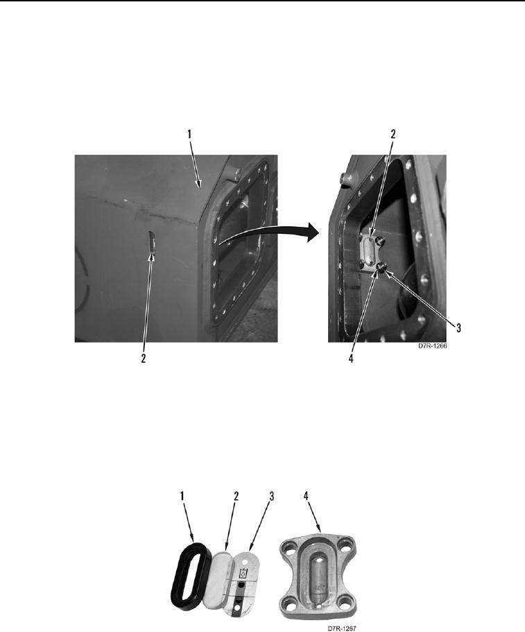
DISASSEMBLY CONTINUED
N OT E
Note orientation of level gauge to aid installation.
33. Remove four locknuts (Figure 17, Item 3), washers (Figure 17, Item 4), and level gauge (Figure 17, Item 2)
from hydraulic tank (Figure 17, Item 1). Discard locknuts.
Figure 17. Hydraulic Tank Level Gauge.
0187
N OT E
Note orientation of level gauge components to aid installation.
34. Remove gasket (Figure 18, Item 1) and plate (Figure 18, Item 3) from level gauge housing (Figure 18, Item 4).
35. Remove sight glass (Figure 18, Item 2) from gasket (Figure 18, Item 1). Discard gasket.
Figure 18. Level Gauge.
0187