
TM 5-2410-241-23-2
0187
DISASSEMBLY CONTINUED
29. Remove fitting (Figure 16, Item 5) from hydraulic tank (Figure 16, Item 1).
30. Remove two O-rings (Figure 16, Item 6) from fitting (Figure 16, Item 5). Discard O-rings.
N OT E
Note position of harness clips to aid assembly.
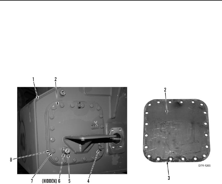
31. Remove 20 bolts (Figure 16, Item 8), washers (Figure 16, Item 7), three harness clips (Figure 16, Item 4), and
cover plate (Figure 16, Item 2) from hydraulic tank (Figure 16, Item 1).
32. Remove gasket (Figure 16, Item 3) from cover plate (Figure 16, Item 2). Discard gasket.
Figure 16. Hydraulic Tank Front Cover Plate.
0187