
TM 5-2410-241-23-3
0209
REMOVAL CONTINUED
N OT E
Note harness routing to aid installation.
Tag and mark all electrical connections to aid installation.
Note number and location of tiedown straps to aid installation.
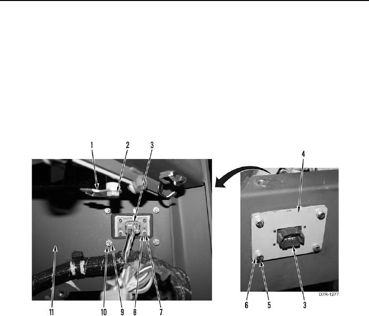
5. Remove four bolts (Figure 3, Item 7), washers (Figure 3, Item 8), and connector (Figure 3, Item 3) from plate
(Figure 3, Item 4). Position connector aside.
6. Remove four nuts (Figure 3, Item 10), washers (Figure 3, Item 9), bolts (Figure 3, Item 5), washers (Figure 3,
Item 6), and plate (Figure 3, Item 4) from platform (Figure 3, Item 11).
7. Remove bolt (Figure 3, Item 2) and two connector brackets (Figure 3, Item 1) from platform (Figure 3, Item 11).
Figure 3. Harness Connector, Plate, and Clip.
0209