
6
TM 5-2410-241-23-3
FIELD MAINTENANCE INSTRUCTIONS
WIPER CONTROL PLATE AND SWITCHES REPLACEMENT
0234
Removal, Cleaning and Inspection, Installation
INITIAL SETUP
Equipment Condition
Tools and Special Tools
0
0
Tool Kit, General Mechanic's
Machine parked (TM 5-2410-241-10)
0
(WP 0302, Item 65)
0
Drawing Required
0
Materials/Parts
0
TM 5-2410-241-24P, Figure 108
0
Rag, Wiping (WP 0303, Item 24)
0
Estimated Time to Complete
0
Tag, Marker (WP 0303, Item 34)
0
1.0 Hr
0
Tiedown Strap (WP 0303, Item 36)
0
Lockwasher (4)
0
References
0
0
REMOVAL
000234
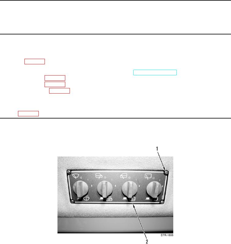
1. Remove four screws (Figure 1, Item 1) from wiper control plate (Figure 1, Item 2).
Figure 1. Wiper Control Plate Assembly.
0234