
TM 5-2410-241-23-3
0234
REMOVAL CONTINUED
N OT E
Steps 7 - 8 will remove one wiper switch. Follow same steps for each additional wiper
switch.
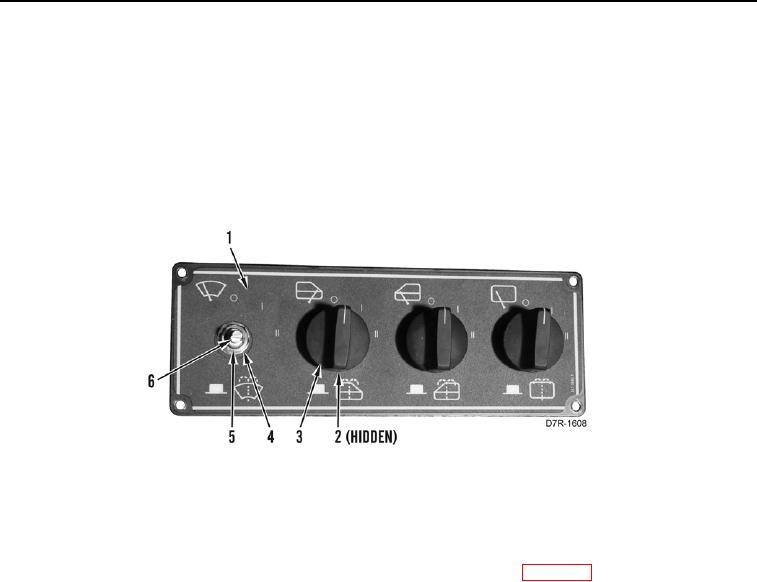
7. Remove setscrew (Figure 3, Item 2) and knob (Figure 3, Item 3) from wiper control plate (Figure 3, Item 1).
8. Remove nut (Figure 3, Item 5), lockwasher (Figure 3, Item 4), and wiper switch (Figure 3, Item 6) from wiper
control plate (Figure 3, Item 1). Discard lockwasher.
Figure 3. Wiper Control Switches.
0234
END OF TASK
CLEANING AND INSPECTION
000234
Clean and inspect all parts IAW Mechanical General Maintenance Instructions (WP 0295).
END OF TASK
INSTALLATION
000234
N OT E
Steps 1 - 2 will install one wiper switch. Follow same steps for each additional wiper
switch.
1. Install wiper switch (Figure 3, Item 6), new lockwasher (Figure 3, Item 4), and nut (Figure 3, Item 5) on wiper
control plate (Figure 3, Item 1).
2. Install knob (Figure 3, Item 3) and setscrew (Figure 3, Item 2) on wiper control plate (Figure 3, Item 1).