
TM 5-2410-241-23-3
0234
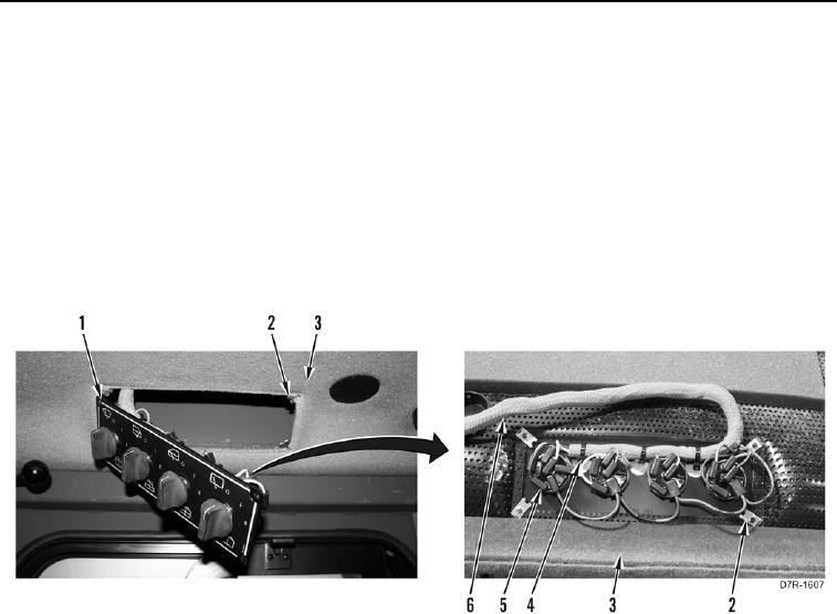
REMOVAL CONTINUED
N OT E
Tag all electrical connectors to aid installation.
2. Position wiper control panel (Figure 2, Item 1) from headliner (Figure 2, Item 3).
3. Disconnect 21 harness connectors (Figure 2, Item 5) from wiper control panel (Figure 2, Item 1).
4. Remove tiedown straps (Figure 2, Item 4) from wiring harness (Figure 2, Item 6) and wiper control panel
(Figure 2, Item 1). Discard tiedown straps.
5. Remove wiper control panel (Figure 2, Item 1) from machine.
6. Remove four speed nuts (Figure 2, Item 2) from headliner (Figure 2, Item 3).
Figure 2. Wiper Control Wiring Harness.
0234