
TM 5-2410-241-23-3
0234
INSTALLATION CONTINUED
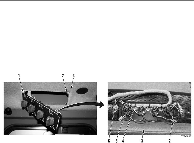
3. Install four speed nuts (Figure 4, Item 2) on headliner (Figure 4, Item 3).
4. Position wiper control panel (Figure 4, Item 1) on wiring harness (Figure 4, Item 6).
5. Install new tiedown straps (Figure 4, Item 4) on wiring harness (Figure 4, Item 6) and wiper control panel
(Figure 4, Item 1).
N OT E
Install all electrical connectors as noted during removal.
6. Connect 21 harness connectors (Figure 4, Item 5) on wiper control panel (Figure 4, Item 1)
7. Position wiper control panel (Figure 4, Item 1) on headliner (Figure 4, Item 3).
Figure 4. Wiper Control Wiring Harness.
0234