
TM 5-2410-241-23-3
0262
DISASSEMBLY CONTINUED
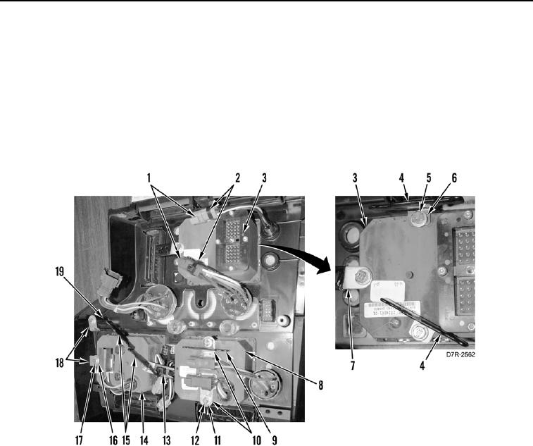
3. Remove and discard tiedown straps (Figure 7, Item 2) from connectors (Figure 7, Item 1).
4. Remove three bolts (Figure 7, Item 5), washers (Figure 7, Item 6), two brackets (Figure 7, Item 4), and clips
(Figure 7, Item 7) from gauge (Figure 7, Item 3).
5. Remove two bolts (Figure 7, Item 12), washers (Figure 7, Item 11), bracket (Figure 7, Item 9), and two clamps
(Figure 7, Item 10) from gauge (Figure 7, Item 8).
6. Remove four bolts (Figure 7, Item 17), washers (Figure 7, Item 16), two brackets (Figure 7, Item 15), clip
(Figure 7, Item 13), and three clamps (Figure 7, Item 18) from gauge (Figure 7, Item 14) and post (Figure 7,
Item 19).
Figure 7. Connector Clamps and Brackets.
0262