Home
Download PDF
Order CD-ROM
Order in Print
Figure 7. Connector Clamps and Brackets.
Figure 9. Upper Half of Instrument Panel.
Field Maintenance Manual 3 D7R Dozer Type I With Winch and Type II With Ripper
Page Navigation
714
715
716
717
718
719
720
721
722
723
724
TM
5-2410-241-23-3
0262
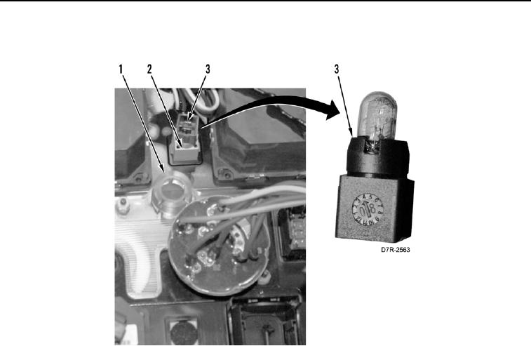
DISASSEMBLY
CONTINUED
7.
Remove
indicator
bulb
(
Figure
8,
Item
3)
from
holder
(
Figure
8,
Item
2)
and
instrument
panel
(
Figure
8,
Item
1).
Figure 8.
Indicator
Bulb.
0262
0262-8