
TM 5-2410-241-23-3
0262
DISASSEMBLY CONTINUED
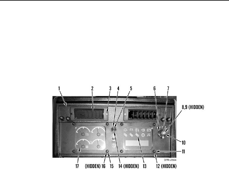
8. Remove four screws (Figure 9, Item 3) and two louvers (Figure 9, Item 2) from instrument panel (Figure 9,
Item 1).
9. Remove two nuts (Figure 9, Item 4), lockwashers (Figure 9, Item 14), and two switches (Figure 9, Item 5) from
instrument panel (Figure 9, Item 1). Discard lockwashers.
10. Remove screw (Figure 9, Item 8), lockwasher (Figure 9, Item 9), knob (Figure 9, Item 7), nut (Figure 9, Item 6),
and ignition switch (Figure 9, Item 10) from instrument panel (Figure 9, Item 1). Discard lockwashers.
11. Remove four screws (Figure 9, Item 11), washers (Figure 9, Item 12), and gauge (Figure 9, Item 13) from
instrument panel (Figure 9, Item 1).
12. Remove four screws (Figure 9, Item 15), washers (Figure 9, Item 16), and gauge (Figure 9, Item 17) from
instrument panel (Figure 9, Item 1).
Figure 9. Upper Half of Instrument Panel.
0262