
TM 5-2410-241-23-3
0262
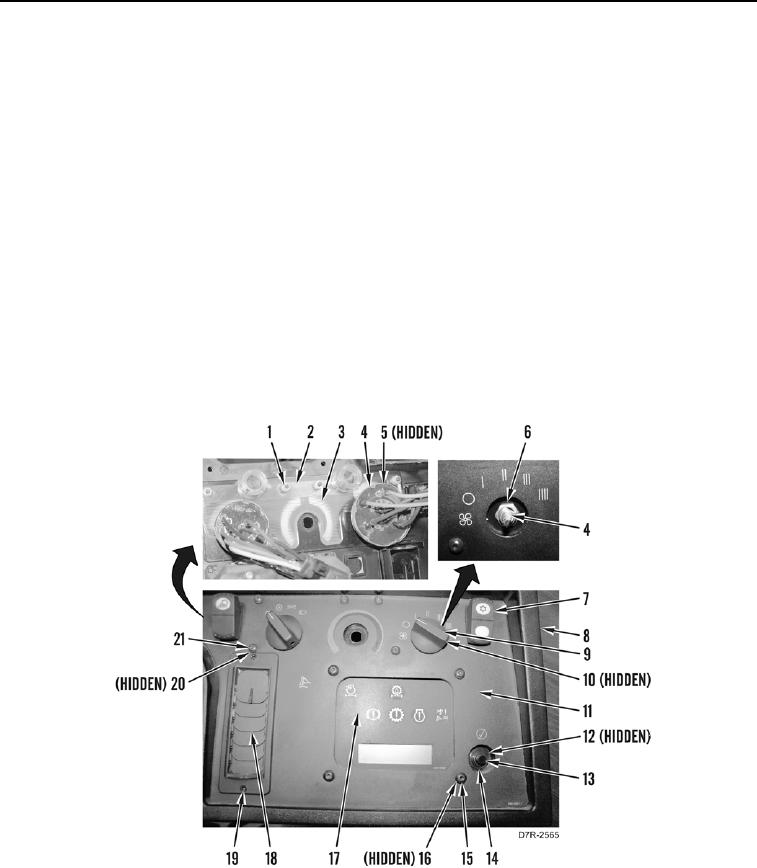
DISASSEMBLY CONTINUED
N OT E
Note position and orientation of spacers to aid installation.
13. Loosen two setscrews (Figure 10, Item 10) and remove two knobs (Figure 10, Item 9), nuts (Figure 10, Item 6)
selector switches (Figure 10, Item 4), and spacers (Figure 10, Item 5) from instrument panel (Figure 10,
Item 8).
14. Remove two switches (Figure 10, Item 7) from instrument panel (Figure 10, Item 8).
15. Remove six screws (Figure 10, Item 21), washer (Figure 10, Item 20), nuts (Figure 10, Item 1), plate
(Figure 10, Item 2), and deflector (Figure 10, Item 3) from instrument panel (Figure 10, Item 8).
16. Remove nut (Figure 10, Item 14), lockwasher (Figure 10, Item 12), and switch (Figure 10, Item 13) from
instrument panel (Figure 10, Item 8). Discard lockwasher.
17. Remove four screws (Figure 10, Item 15), washers (Figure 10, Item 16), and gauge (Figure 10, Item 17) from
instrument panel (Figure 10, Item 8).
18. Remove six screws (Figure 10, Item 19) and three louvers (Figure 10, Item 18) from instrument panel
(Figure 10, Item 8).
19. Remove two display decals (Figure 10, Item 11) from instrument panel (Figure 10, Item 8). Discard decals.
Figure 10. Lower Half of Instrument Panel.
0262