
TM 5-2410-241-23-3
0266
INSTALLATION CONTINUED
N OT E
Install tubes and fittings as noted during removal.
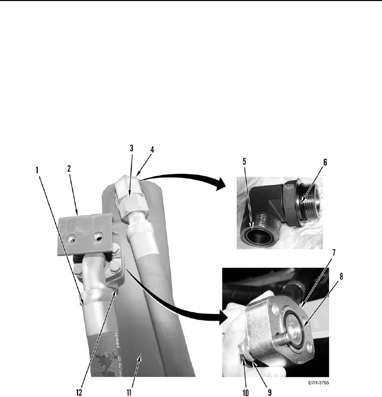
8. Install two new O-rings (Figure 9, Items 5 and 6) on elbow (Figure 9, Item 4).
9. Install elbow (Figure 9, Item 4) on lift cylinder (Figure 9, Item 11).
10. Connect hose (Figure 9, Item 3) to elbow (Figure 9, Item 4).
11. Install new O-ring (Figure 9, Item 7) and clamp (Figure 9, Item 8) on hose (Figure 9, Item 1).
12. Connect hose (Figure 9, Item 1) to lift cylinder tube (Figure 9, Item 12) and install four washers
(Figure 9, Item 9), bracket (Figure 9, Item 2), and bolts (Figure 9, Item 10).
Figure 9. Upper Hose Connection.
0266