
TM 5-2410-241-23-3
0266
INSTALLATION CONTINUED
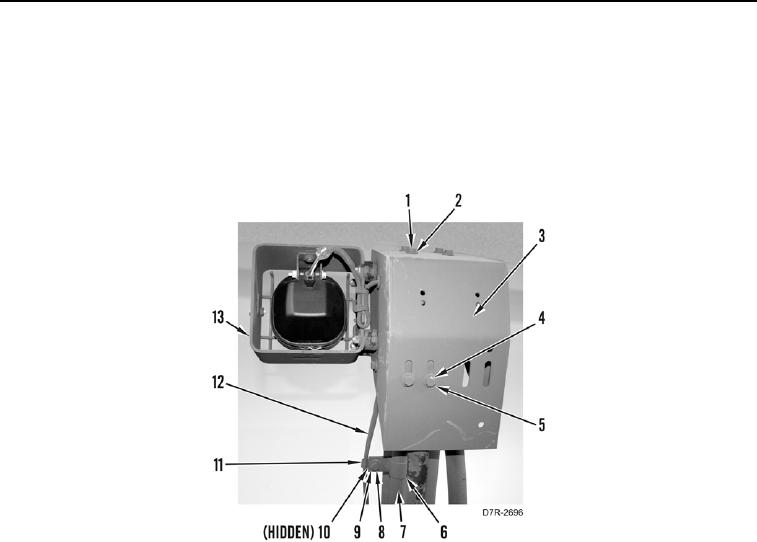
13. Position harness (Figure 10, Item 12), cover (Figure 10, Item 3), light (Figure 10, Item 13), two washers
(Figure 10, Item 5), and bolts (Figure 10, Item 4) on machine.
14. Install four washers (Figure 10, Item 2) and bolts (Figure 10, Item 1) on cover (Figure 10, Item 3).
15. Install four flanges (Figure 10, Item 6), two harness clips (Figure 10, Item 11), four washers (Figure 10, Item 9),
two nuts (Figure 10, Item 10), and bolts (Figure 10, Item 8) on tube (Figure 10, Item 7).
Figure 10. Upper Hose Connection Cover.
0266
END OF TASK
FOLLOW-ON TASKS
000266
Verify correct operation of machine (TM 5-2410-241-10).
END OF TASK
END OF WORK PACKAGE