
TM 5-2410-241-23-3
0268
INSTALLATION
000268
1. Drive machine into position on blade assembly (TM 5-2410-241-10).
N OT E
Install nut in same orientation noted during removal.
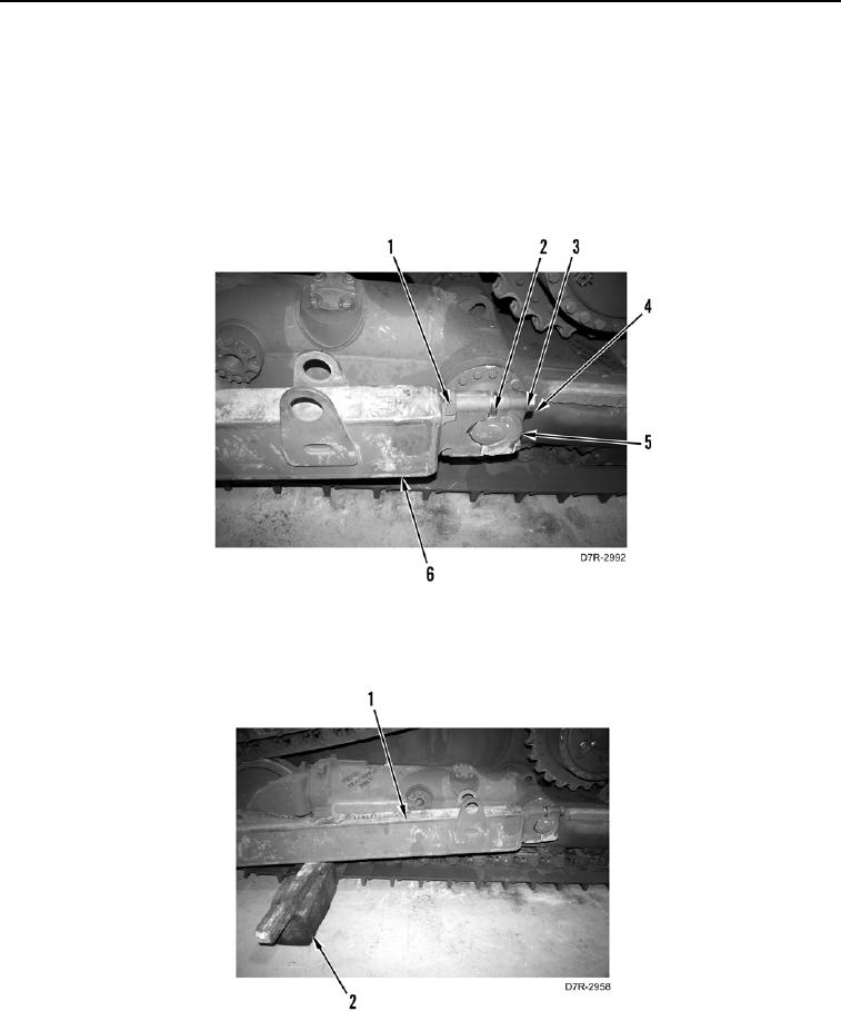
2. Install half-yoke (Figure 18, Item 5), shim pack (Figure 18, Item 2), two washers (Figure 18, Item 3), bolts
(Figure 18, Item 4), and nuts (Figure 18, Item 1) on machine. Repeat step 2 for other side.
Figure 18. Push Arm Yoke.
0268
3. Remove all blocks (Figure 19, Item 2) under push arms (Figure 19, Item 1).
Figure 19. Push Arm.
0268