
TM 5-2410-241-23-3
0268
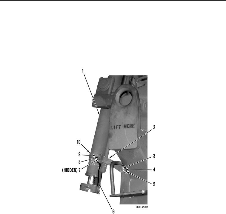
INSTALLATION CONTINUED
4. Remove retaining clamps from lift cylinders (Figure 20, Item 1).
a. Remove bolt (Figure 20, Item 9), two washers (Figure 20, Item 7), nut (Figure 20, Item 8), and two half-
clamps (Figure 20, Item 10) from lift cylinder (Figure 20, Item 1).
b. Remove bolt (Figure 20, Item 3), washer (Figure 20, Item 4), spacer (Figure 20, Item 5), and bar
(Figure 20, Item 2).
c.
Cut and discard two heavy duty tiedown straps (Figure 20, Item 6) from lift cylinder (Figure 20, Item 1).
d. Repeat substeps a through c for other lift cylinder (Figure 20, Item 1).
Figure 20. Retaining Clamps.
0268