
TM 5-2410-241-23-3
0269
INSTALLATION
000269
WARN I N G
Use extreme caution when handling heavy parts. Provide adequate support and use
assistance during procedure. Ensure lifting device used is in good condition and of
suitable load capacity. Keep clear of heavy parts supported only by lifting device. Failure
to follow this warning may cause injury or death to personnel.
N OT E
Center blade cutting edges weigh 90 lb (41 kg) each.
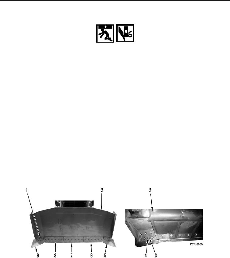
1. With assistance, install right center blade cutting edge (Figure 4, Item 8), six bolts (Figure 4, Item 1), washers
(Figure 4, Item 4), and nuts (Figure 4, Item 3) on blade assembly (Figure 4, Item 2).
2. With assistance, install left center blade cutting edge (Figure 4, Item 6), six bolts (Figure 4, Item 1), washers
(Figure 4, Item 4), and nuts (Figure 4, Item 3) on blade assembly (Figure 4, Item 2).
3. With assistance, install center blade cutting edge (Figure 4, Item 7), six bolts (Figure 4, Item 1), washers
(Figure 4, Item 4), and nuts (Figure 4, Item 3) on blade assembly (Figure 4, Item 2).
N OT E
Corner blade cutting edges weigh 70 lb (32 kg) each.
4. With assistance, install left corner blade cutting edge (Figure 4, Item 5), seven bolts (Figure 4, Item 1), washers
(Figure 4, Item 4), and nuts (Figure 4, Item 3) on blade assembly (Figure 4, Item 2).
5. With assistance, install right corner blade cutting edge (Figure 4, Item 9), seven bolts (Figure 4, Item 1),
washers (Figure 4, Item 4), and nuts (Figure 4, Item 3) on blade assembly (Figure 4, Item 2).
Figure 4. Blade Cutting Edges.
0269