
TM 5-2410-241-23-3
0269
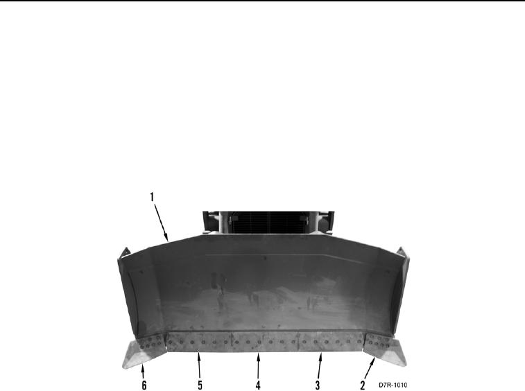
BLADE CUTTING EDGE ROTATION
000269
1. If blade left corner cutting edges (Figure 6, Items 2) and right corner cutting edges (Figure 6, Items 6) are worn
down to bottom of blade assembly (Figure 3, Item 1), replace blade corner cutting edges. Refer to Removal
and Installation in this work package.
2. Remove three center blade cutting edges (Figure 6, Items 3, 4, and 5) from blade assembly (Figure 6, Item 1).
Refer to Removal in this work package.
3. With worn edge facing up, position center blade cutting edge (Figure 6, Item 4) on blade assembly (Figure 6,
Item 1). Refer to Installation in this work package.
4. With worn edges facing up, switch positions of left center blade cutting edge (Figure 6, Items 3) and right
center blade cutting edge (Figure 6, Items 5) on blade assembly (Figure 6, Item 1). Refer to Installation in this
work package.
Figure 6. Cutting Edge Rotation.
0269
END OF TASK
FOLLOW-ON TASKS
000269
Verify correct operation of machine (TM 5-2410-241-10).
END OF TASK
END OF WORK PACKAGE