
TM 5-2410-241-23-3
0282
INSTALLATION CONTINUED
WARN I N G
Use extreme caution when handling heavy parts. Provide adequate support and use
assistance during procedure. Ensure lifting device used is in good condition and of
suitable load capacity. Keep clear of heavy parts supported only by lifting device. Failure
to follow this warning may cause injury or death to personnel.
N OT E
Use suitable lifting device to support ripper tilt cylinder. The ripper tilt cylinder weighs
approximately 250 lb (113 kg).
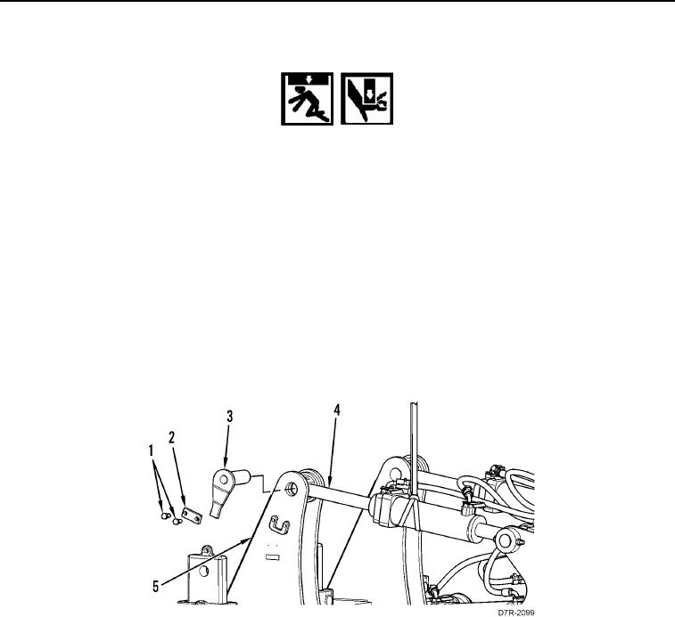
9. Install pin assembly (Figure 7, Item 3), plate (Figure 7, Item 2), and bolts (Figure 7, Item 1) on ripper tilt cylinder
(Figure 7, Item 4) and ripper carriage (Figure 7, Item 5). Tighten bolts to 340 45 lb ft (460 60 Nm).
10. Remove lifting straps from ripper tilt cylinder (Figure 7, Item 4).
11. Repeat steps 8 through 10 for other ripper tilt cylinder (Figure 7, Item 4).
12. Remove wood block.
Figure 7. Ripper Tilt Cylinder Rod End.
0282