
TM 5-2410-241-23-3
0287
ARCTIC KIT BATTERY CABLES INSTALLATION CONTINUED
5. Install two grommets (Figure 14, Item 5) on arctic kit battery box (Figure 14, Item 6) and battery box (Figure 14,
Item 7).
N OT E
Install cables as noted during removal.
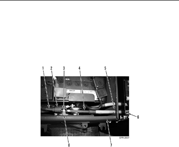
6. Install positive arctic kit battery cable (Figure 14, Item 4) on machine.
7. Install positive arctic kit battery cable (Figure 14, Item 4), positive cable (Figure 14, Item 1), and nut (Figure 14,
Item 3) on terminal (Figure 14, Item 8).
8. Position positive cable cover (Figure 14, Item 2) on terminal (Figure 14, Item 8).
Figure 14. Positive Battery Cables at Terminal.
0287