
TM 5-2410-241-23-3
0287
ARCTIC KIT BATTERY CABLES INSTALLATION CONTINUED
N OT E
Install cables as noted in removal.
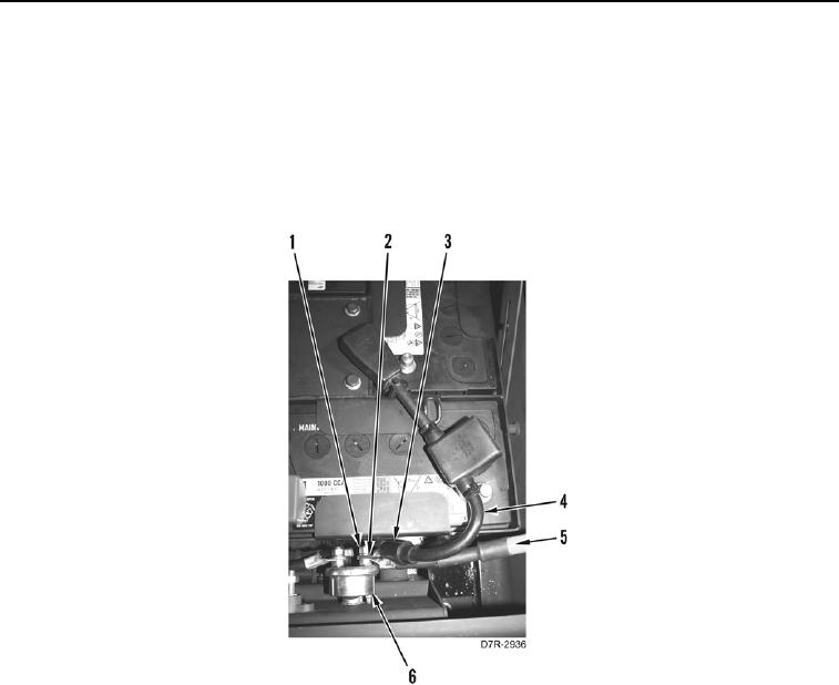
3. Install negative arctic kit battery cable (Figure 13, Item 5), negative battery cable (Figure 13, Item 4), washer
(Figure 13, Item 2), and nut (Figure 13, Item 1) on disconnect switch (Figure 13, Item 6).
4. Position negative cable cover (Figure 13, Item 3) over nut.
Figure 13. Negative Battery Cables at Disconnect Switch.
0287