
TM 5-2410-241-23-3
0287
ARCTIC KIT JUNCTION BLOCK POWER CABLE REMOVAL
000287
1. Position positive cable cover (Figure 8, Item 2) aside.
N OT E
Note cable routing to aid installation.
Tag and mark all electrical connections and cables to aid installation.
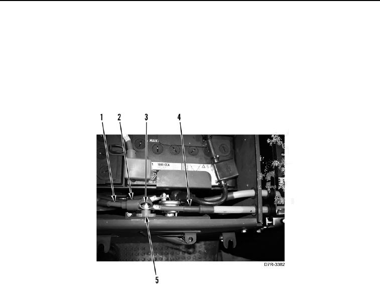
2. Remove nut (Figure 8, Item 3), arctic kit junction block positive cable (Figure 8, Item 1) and positive arctic kit
battery cable (Figure 8, Item 4) from terminal (Figure 8, Item 5). Position cables aside.
Figure 8. Arctic Kit Positive Battery Cable at Terminal.
0287