
TM 5-2410-241-23-3
0287
ARCTIC KIT BATTERY CABLES REMOVAL CONTINUED
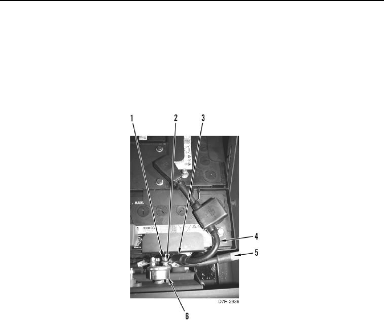
16. Position negative cable cover (Figure 6, Item 3) aside.
N OT E
Note cable routing to aid installation.
Tag and mark all cables to aid installation.
17. Remove nut (Figure 6, Item 1), washer (Figure 6, Item 2), negative battery cable (Figure 6, Item 4) and
negative arctic kit battery cable (Figure 6, Item 5) from disconnect switch (Figure 6, Item 6).
Figure 6. Negative Battery Cables at Disconnect Switch.
0287