
TM 5-2410-241-23-3
0297
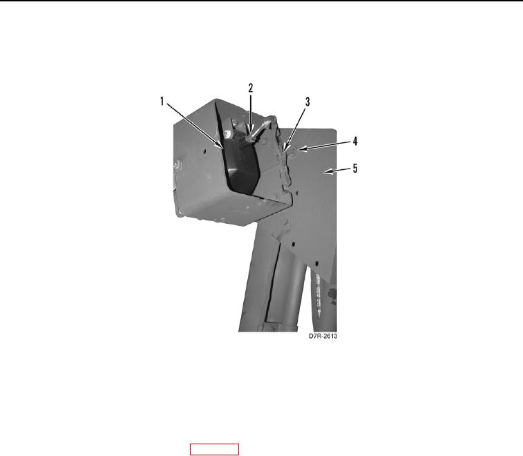
LIFT CYLINDER INSTALLATION CONTINUED
11. Route wiring harness and connector (Figure 45, Item 2) through hole in bracket (Figure 45, Item 5) and seal
grommet (Figure 45, Item 4).
Figure 45. Floodlamp Wiring Harness Connector.
0297
12. Connect wiring harness connector (Figure 45, Item 2) to floodlamp (Figure 45, Item 1).
13. Using tiedown straps (Figure 45, Item 3), secure wiring harness in two locations.
14. Repeat steps 9 through 13 on other side of machine.
15. Install trunnions (WP 0130).
16. Assemble and install bulldozer blade (WP 0268).
17. Check and fill hydraulic fluid level (WP 0184).
18. Verify correct operation of machine (TM 5-2410-241-10).
END OF TASK