
TM 5-2410-241-23-3
0297
TOWING WITH ENGINE STOPPED CONTINUED
0297
N OT E
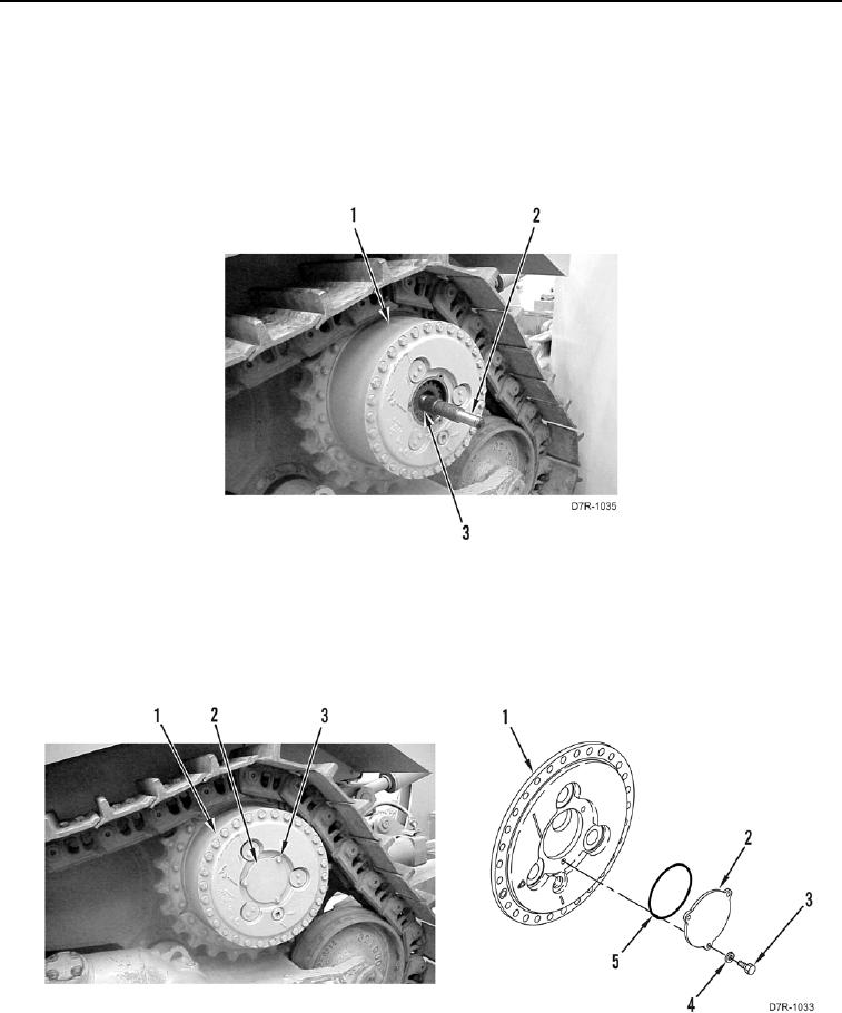
Note orientation and position of axle shaft to aid installation.
3. Using adapter (Figure 48, Item 2), remove outer axle shaft (Figure 48, Item 3) from drive assembly (Figure 48,
Item 1).
Figure 48. Outer Axle Shaft.
0297
4. Install O-ring (Figure 49, Item 5), cap (Figure 49, Item 2), three washers (Figure 49, Item 4) and bolts (Figure
49, Item 3) on drive assembly (Figure 49, Item 1). Discard O-ring.
5. Repeat steps 1-4 for right side axle shaft.
Figure 49. Axle Cap.
0297