
18
TM 5-2410-240-23-1
FIELD MAINTENANCE
-
THEORY OF OPERATION HYDRAULICS
0007
HYDRAULIC SYSTEMS
0007
Hydraulic Fan
0007
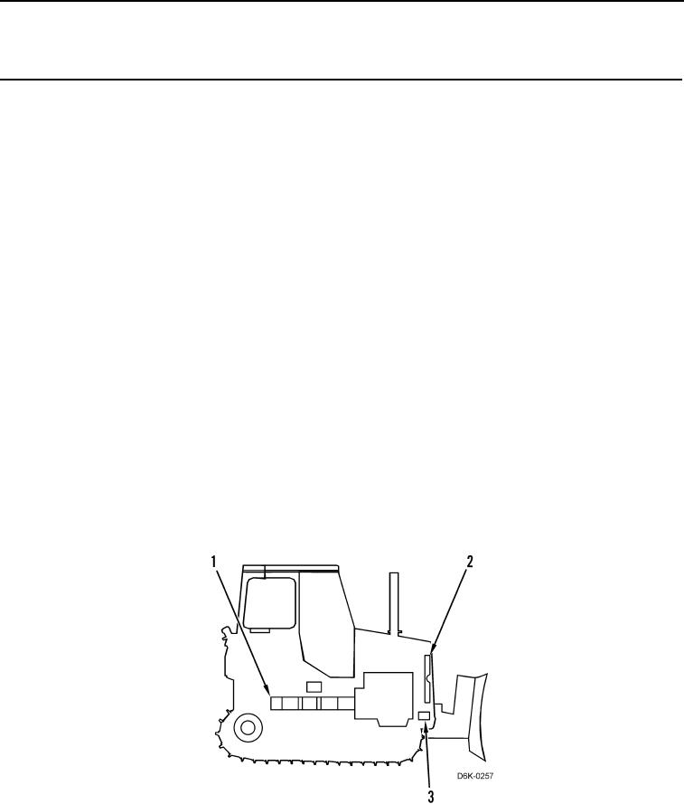
The hydraulic fan system uses a fixed-displacement hydraulic pump (Figure 1, Item 1) to drive a fixed-
displacement fan drive gear motor (Figure 1, Item 2). The fan system has variable speeds, even though the pump
and motor have fixed displacements. The flow control valve inside the fan control manifold (Figure 1, Item 3)
controls the flow of hydraulic oil to the fan drive gear motor, which controls the fan speed. The demand fan
solenoid on the fan control manifold controls the flow control valve. Electric current from the machine Electronic
Control Module (ECM) controls the demand fan solenoid.
The machine ECM determines proper fan operation based on hydraulic oil temperature, engine coolant
temperature, and inlet manifold temperature. The engine ECM communicates inlet manifold temperature and
engine coolant temperature to the machine ECM. Data from the hydraulic oil temperature sensor goes directly to
the machine ECM.
When the operator starts the engine, the fixed displacement hydraulic pump (Figure 1, Item 1) draws hydraulic oil
from the tank. When fan operation is necessary, the engine ECM sends a request to the machine ECM to signal
the demand fan solenoid. In turn, the machine ECM supplies the appropriate electric current to the demand fan
solenoid to start closing the flow control valve. This restricts the flow of oil through the valve. With the oil flow
restricted, oil must flow through the fan drive gear motor (Figure 1, Item 2). This causes the fan drive gear motor to
turn faster. When the machine requires more airflow for cooling, it further decreases the electric current to the
demand fan solenoid in order to close the flow control valve more.
When the machine requires less airflow for cooling, the machine ECM increases the amount of electric current to
the demand fan solenoid in order to open the flow control valve more. This increases the flow of oil through the flow
control valve, which decreases the flow of oil through the fan drive gear motor (Figure 1, Item 2). This causes the
fan drive gear motor to turn more slowly. A makeup valve inside the fan control manifold (Figure 1, Item 3) prevents
cavitation in the fan drive gear motor during deceleration.
Figure 1. Hydraulic Fan System.
0007