Home
Download PDF
Order CD-ROM
Order in Print
Figure 4. Diagnostic Connector.
Figure 6. What's New Dialog Box.
Field Maintenance Manual 1 D6K Dozer Type I With Winch and Type II With Ripper
Page Navigation
147
148
149
150
151
152
153
154
155
156
157
TM
5-2410-240-23-1
0016
SOFTWARE
INSTALLATION
AND
CONNECTING
MSD
CONTINUED
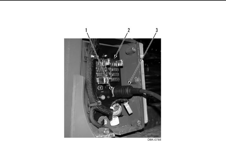
9.
Connect
cable
(Figure
5,
Item
3) to
diagnostic
connector
(Figure
5,
Item
1) on
fuse
panel
(Figure
5,
Item
2).
Figure 5.
Diagnostic
Connector
and
Fuse Panel.
0016
0016-5