
TM 5-2410-240-23-1
0028
AIR INLET AND EXHAUST SYSTEM INSPECTION
00028
Air Cleaner, Air Inlet, and Check Valve Inspection
00028
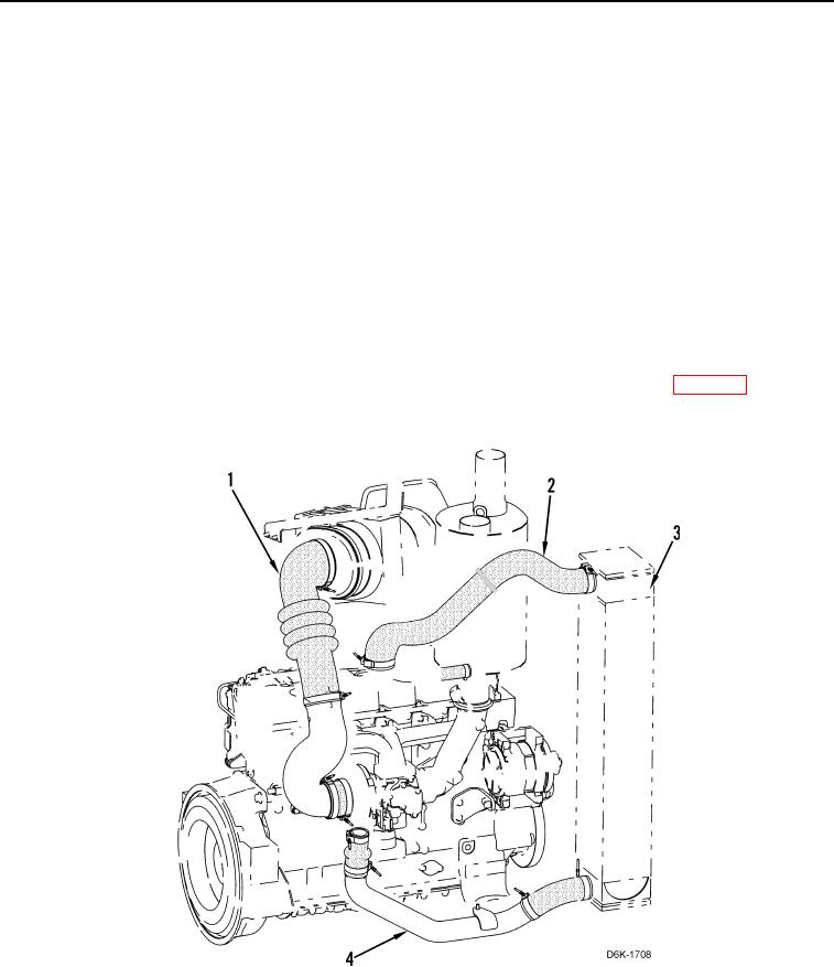
1. Inspect engine air cleaner outlet hose and tube (Figure 1, Item 1), turbocharger outlet hose and tube (Figure 1,
Item 4), and charge air cooler outlet hose (Figure 1, Item 2) for restrictions, collapse, and damage. Replace air
inlet hoses if condition found (WP 0041).
2. Inspect turbocharger outlet hose and tube (Figure 1, Item 4), and turbocharger aftercooler (Figure 1, Item 3) for
evidence of oil.
a. If oil is found, inspect turbocharger outlet hoses and determine cause of oil. Refer to Turbocharger
Inspection in this work package.
b. Clean turbocharger outlet hose and tube (Figure 1, Item 4), and turbocharger aftercooler (Figure 1, Item 3)
(WP 0041).
3. Inspect turbocharger aftercooler (Figure 1, Item 3) for blockage and debris on cooling fins. Blockage of airflow
to aftercooler will increase intake air temperature and may cause engine ECM to derate engine power and set
an event code.
E539-1 will set and display on Messenger and ET. Code will set when intake air temperature exceeds
179F (82C) for more than three minutes. No action by ECM will be taken. Refer to WP 0019.
Figure 1. Air Hoses and Charge Air Cooler.
0028