
TM 5-2410-240-23-2
0039
REMOVAL CONTINUED
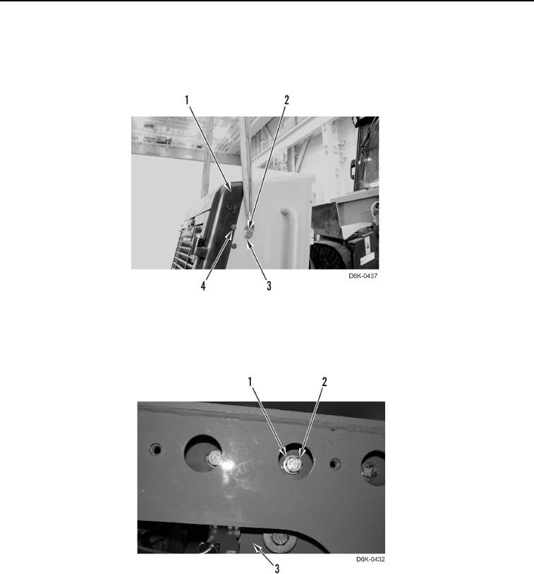
15. Remove two plugs (Figure 6, Item 4) from cooling module (Figure 6, Item 1).
16. Install two bracket links (Figure 6, Item 3), bolts (Figure 6, Item 2), and lifting device on cooling module
(Figure 6, Item 1). Support cooling module.
Figure 6. Lifting Device on Cooling Module.
0039
17. Remove six bolts (Figure 7, Item 2) and washers (Figure 7, Item 1) retaining cooling module (Figure 7, Item 3)
on machine.
Figure 7. Cooling Module and Bottom Mounting Bolts.
0039